

The complex interplay takes place between vibrationally and electronically excited states in the active medium of Oxygen-Iodine Laser (OIL). The energy levels of I, O2, I2 and H2O that most significantly involved in the kinetics of OIL active medium are exhibited in Fig. 1.
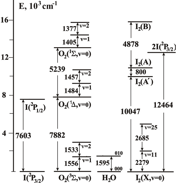
Fig. 1. The energies of the lower lying levels of O2, I2, H2O and I.
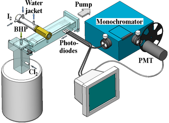
Fig. 2. The low-pressure flow cell apparatus with a jet-type SOG.
Singlet oxygen was generated in a jet
singlet oxygen generator (SOG). The gas pressure Pg in the reaction zone
of the SOG was about 35 Torr. Oxygen was supplied from the SOG to a measuring
cell. Iodine vapour with a carrier gas (N2) was injected into
the oxygen flow. The gas pressure Pc in the measuring cell was
≈ 3 Torr. Figure 3 presents the emission spectra of
O2(b) in the wavelength range from 757 to 785 nm for two
initial molecular fraction of iodine in the flow. The observation point
was located down-stream at a distance of L =
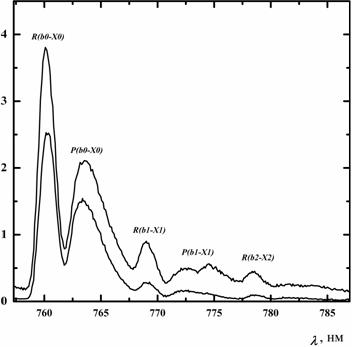
The symbols R(bi-Xi) and P(bi-Xi) in Fig. 3 denote the contours of rotational R and P branches for three transitions O2(b1Σ,υ=i)→O2(X3Σ,υ=i)+hv. The fraction of vibrationally excited O2(b1Σ) molecules for the first and second vibrational levels at maximum was 22% and 10%, respectively. The redistribution of vibrational quanta between oxygen molecules O2(X3Σ), O2(a1Δ) and O2(b1Σ) occurs during rapid EE-exchange processes. As a result, the average number of vibrational quanta per each oxygen molecule [O2(X3Σ), O2(a1Δ) or O2(b1Σ)] is virtually the same (Antonov I.O. et al. J. Chem. Phys., vol. 119, 2003, p. 10638-10646, doi: 10.1063/1.1621620).
Dissociation channels of I2 in the presence of singlet oxygen molecules O2(a1Δ). The mechanism by which singlet oxygen O2(a1Δ) dissociates I2 remains as an important unsolved problem for the oxygen iodine laser (OIL). It is well known that the I2 dissociation process has initiation and chain propagation stages, and that excited intermediate states of iodine are involved [Azyazov V.N., Quantum Electronics, vol. 39, 2009, p. 989-1007, doi: 10.1070/QE2009v039n11ABEH014014]. There are unresolved questions concerning the identity of the intermediates and the excitation pathways involved in both the initiation and chain propagation reactions. These and some additional details of the I2 dissociation mechanism in the COIL medium are still uncertain, but it has been established that a complex interplay between vibrationally and electronically excited states of I2 and O2 is involved.
This long-standing problem was a primary objective of the U.S. Civilian Research & Development Foundation (CRDF) grant “Determination of dominant I2 dissociation pathway in singlet oxygen” (Award Number: RC1-2516-SA-03) that was performed by joint research teams of U.S. (Emory University, Principal Investigator Michael Heaven) and former Soviet Union (FSU) (Samara branch of P.N. Lebedev Physical Institute, Principal Investigator Valeriy Azyazov).
The multiparametric experimental investigation of the dissociation kinetics of iodine in singlet oxygen was performed by the emission method in a low-pressure continuous-flow chamber (Fig. 2). The operation of the system is demonstrated by short films 1 and 2. The jet type singlet oxygen generator (SOG) reaction zone represented a cylindrical cavity
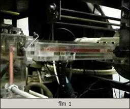
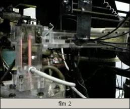
Figure 4. The operation of the low-pressure low-pressure flow tube apparatus. The vertical red stripe is SO dimole emission (634 nm) in the reaction zone of chemical singlet oxygen generator at 30 Torr oxygen pressure. The horizontal red stripes is SO dimol emission in the measuring cell with oxygen pressure 10 Torr (film 1) and broad emission of I2-O2 mixture in the visible range (film 2). Click to download and play.
We recorded the emission bands:
I2(B)→I2(X),
O2(b1Σ)→O2(X3Σ),
I(2P1/2)→I(2P3/2)
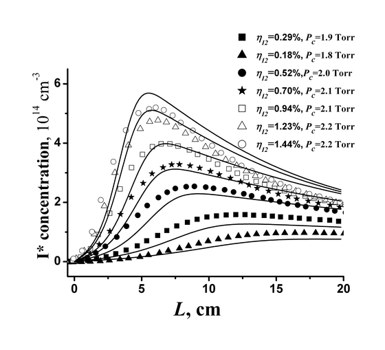
in a broad range of mixture compositions. As an example, Fig. 5 demonstrates
the distributions of the concentration of excited I* atoms along the coordinate
L of the flow for oxygen diluted with nitrogen at the ratio O2:N2
= 1:1, the relative content of water vapours in oxygen 3% and the relative
fraction of
O2(a1Δ)
≈60% for several relative concentrations of I2.
Analysis of the obtained experimental results allowed to reveal the excited intermediates that play active role in the iodine dissociation process and conjecture there excitation mechanisms. The proposed multy-pathways I2 dissociation model predicts with reasonable accuracy the iodine dissociation rates not only in our flow tube experiments but in the real COIL system as well that was developed in Dr. Rosenwaks lab (Israel, Ben-Gurion University of the Negev). It should be particularly emphasized that Dr. Rosenwaks and Dr. Barmashenko contributed much to the development of the I2 dissociation model.
Kinetic studies performed at Emory University in Michael Heaven lab. Firstly, I would like to express to Professor Michael Heaven gratitude for the opportunity to work in his well advanced laboratory. We performed kinetic studies of chemical and energy-exchange processes in O2/O3/I2/CF3I/N2O/NO/NO2 using laser pulse-technique (LPT), laser induced fluorescence (LIF), time-resolved emission spectroscopy (ES) etc. To explore the role of electronically excited I2 on dissociation we measured rate constants for I2(A') quenching by CO2, I2 and Ar. The rate constant for quenching of I2(A') by CO2 was found to be relatively small KCO2 =8.5x10⁻¹³ cm3/s as compared with the rate constant for quenching by O2 - KO2=6.3x10⁻¹² cm3/s. This supports our observation that addition of CO2 into iodine-oxygen mixture in flow tube experiments with dilution ratios up to CO2:O2=3:1 affected insignificantly on the dissociation rate (Azyazov V.N. and Heaven M.C., AIAA Journal, 2006, vol. 44, p. 1593-1600, doi: 10.2514/1.18230).
Oxygen-iodine lasers that utilize electrical or microwave discharges to produce singlet oxygen are currently being developed. In recent years a great stride was made in the development of ElecricOIL. The ElectricOIL output power above 500 W was obtained for the short period of time in Dr. David Carroll's lab. The discharge generators differ from conventional chemical singlet oxygen generators in that they produce significant amounts of atomic oxygen. Post-discharge chemistry includes channels that lead to the formation of ozone. Moreover nitrous oxides are added to increase the production of singlet oxygen molecules. Consequently, removal of I(2Ρ1/2) by O atoms and NO, NO2, N2O2, N2O, O3 molecules may impact the efficiency of discharge driven iodine lasers. We have measured the rate constants for quenching of I(2Ρ1/2) by these components using pulsed laser photolysis technique.
The flow cell shown in Fig. 6 was designed to achieve good mixing of the I2 and O3 streams with a total transit time below 10 ms. The heart of this cell consisted of a
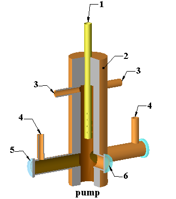
The kinetics were followed by observing the 1315 nm fluorescence from I(2P1/2) as a function of time. Measurement of the ozone quenching rate constant was carried out both for its relevance to the discharge laser system and because O3 was used as the photolytic precursor of O atoms for the measurement of I(2P1/2)+O(3P) quenching. Photolysis of I2 at 485 nm was used as the source of I(2P1/2) for the ozone quenching experiments. At this wavelength the dominant photodissociation channels are
I2(X) + 485nm → I2(B) → I(2P1/2) + I(2P3/2)
→ I2(1u) → I(2P3/2) + I(2P3/2).
The branching ratio for the production of I(2P1/2) atoms is in the range [I(2P1/2)]/(
[I(2P1/2)]+
[I(2P3/2)])=
0.23-0.3. The photolysis of ozone at this wavelength was negligible.
Pulsed laser photolysis of I2/O3/N2
mixtures using 248 or 266 nm light was used to study the quenching of I(2P1/2)
by O(3P) in the presence of O3. Light at these
wavelengths is not absorbed significantly by I2. Excited oxygen atoms and singlet oxygen molecules were the primary photolysis
products
Electronically excited iodine atoms were subsequently produced via EE transfer from O2(a1Δ). To study the quenching of excited iodine atoms I* by nitrous oxides we used the pulsed laser photolysis of CF3I at 245 nm to produce excited iodine atoms.
As example, Fig. 7 shows fluorescence decay curves for I(2P1/2) recorded for a range of ozone partial pressures. All other conditions were held constant, with an I2 vapor pressure 28 mTorr, total gas pressure of Ptot=17 Torr and a temperature of 295 K. The decay curves shown in Fig. 7 exhibited single exponential decay characteristics and allow to define a quenching rate constant.
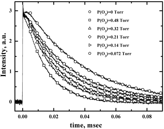
Figure 7. I(2Ρ1/2) fluorescence decay curves recorded for various O3 partial pressures. These curves were obtained using 485 nm laser photolysis of I2/O3/N2 mixtures at Ptot=17 Torr, P(I2)=28 mTorr. Symbols are representative fitted points. (Azyazov V.N. et al. J. Phys. Chem. A., 2007, vol. 111, p. 3010-3015, doi: 10.1021/jp068546g).
The main results:
1. Contributed to the development of Heidner-Lilenfeld-Azyazov-Pichugin-Heaven model of iodine molecule dissociation in the presence of singlet delta oxygen (Azyazov V.N. et al. J. Chem. Phys., vol. 130, 2009, p. 104306(9), doi: 10.1063/1.3081454).
2. Measured vibrational population of oxygen molecules at the output of the SOG and in the oxygen-iodine mixture using emission spectroscopy technique (Antonov I.O. et al. Chem. Phys. Lett., vol. 376, 2003, p. 168-173, doi: 10.1016/S0009-2614(03)00998-9).
3. Measured the rate constant of liquid reaction of chlorine molecule with HO2- and
Cl2 + OH- → k= (6.8±2.7)×10-13 cm3s-1
(Azyazov V.N. et al. Rus. J. Phys. Chem. A, vol. 72, 1998, p. 1681-1685).
4. Measured the following rate constants of chemical and energy exchange processes in the O2/O3/I2/CF3I/CO2/NO2/N2O gaseous mixtures using pulsed laser technique, laser induced fluorescence, emission spectroscopy in the Dr Michael Heaven’s lab:
I2(A') + CO2 → I2(X) + CO2 (8.5±0.9)x10-13 cm3/s
http://arc.aiaa.org/doi/abs/10.2514/1.18230
О2(b1Σ)
+ CO2 →
О2(a1Δ) + CO2
(6.1±0.5)x10-13
cm3/s
http://www.sciencedirect.com/science/article/pii/S0009261409012160
О2(b1Σ)
+ O3
→
products
(1.9±0.2)x10-11
cm3/s
http://www.sciencedirect.com/science/article/pii/S0009261409012160
I(2P1/2)
+ O(3P)
→
I + O(3P)
(1.2±0.1)x10-11
cm3/s
http://pubs.acs.org/doi/abs/10.1021/jp068546g
I(2P1/2)
+ O3 →
products
(1.8±0.4)x10-12
cm3/s
http://pubs.acs.org/doi/abs/10.1021/jp068546g
I(2P1/2)
+ NO2
→
I + NO2
(2.9±0.3)x10-15
cm3/s
http://pubs.acs.org/doi/abs/10.1021/jp0741511
I(2P1/2)
+ N2O4
→
I + N2O4
(3.7±0.5)x10-13
cm3/s
http://pubs.acs.org/doi/abs/10.1021/jp0741511
I(2P1/2)
+ N2O
→
I + N2 O
(1.3±0.1)x10-15
cm3/s